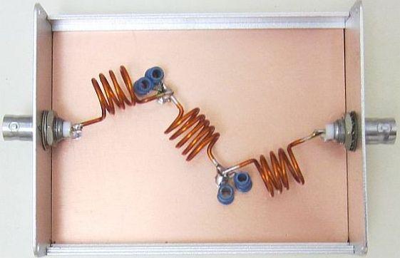
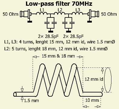
70 MHz LOW-PASS FILTER


INTRODUCTION
To suppress unwanted harmonics, it is recommended to use an extra low-pass filter (LPF) with a 4-meter transmitter. This is especially true for amplifiers with semiconductors and a broadband circuit at the output.
There are several LP filters for the 4 m band on the Internet. This article is about such a simple 5-pole low pass filter with a smaller diameter of the coils.
COILS

The coils were made of 1.5 mm varnished copper wire. I use 12 mm copper («fig) water pipe as a coil bobbin for winding. The internal dimension of the coils remains close to 12 mm. This diameter has been chosen to obtain round numbers for the windings.
Two coils with 4 turns and one with 5 turns are needed, 10 mm long thread ends were left on both sides.
CAPACITORS
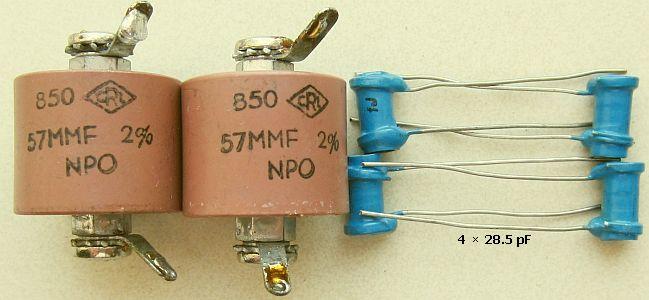
The capacitors used are 28.5 pF. Actually they are 27 pF types, but many in my stock were close to 28.5 pF. Four equal ones of 28.5 pF were selected.
They are well suited for a few hundred watts. For more power, for example, 57 pF "doorknob capacitors" (fig») can be used.
The latter are not chap and are widely used in traps of W3DZZ multiband antennas.
ADJUSTING
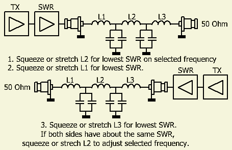
Adjustment is best with the aid of a spectrum analyzer or antenna analyzer.
In the absence of this one can do it as the image (fig») shows:
Load the filter on one side with 50 Ohm and on the other side supply a carrier wave via a SWR meter. By pressing or pulling out the coils, the lowest possible SWR is adjusted in the middle of the 4m band. Then switch the input and output and repeat the procedure. Continue until the same result is obtained on both sides.
1. Sqeeze or stretch L2 for the lowest SWR on the selected frequency.
2. Do the same with L1 for the lowest SWR.
3. Exchange transmitter plus SWR meter with the 50 Ohm load.
4. Sqeeze or stretch L3 for the lowest SWR.
The adjustment of L1 and L3 can be repeated a few times in order to be as close as possible.
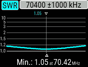
For my case the difference is SWR = 1.05 and SWR = 1.06. Maybe it could be better, but I didn't bother.
Readjust L2 if the frequency deviates from the originally selected value.
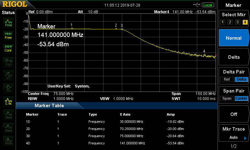
Filter without lid.
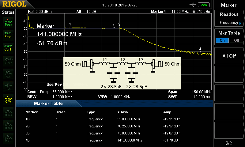
With lid -3dBm worse at 141 MHz.
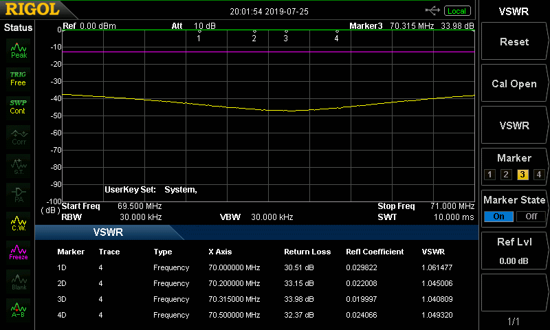
This is the result of the simple 5-pole system. A better suppression is obtained with a 7-pole low-pass filter.
SHIELDING
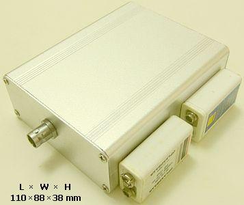
If the filter is mounted in a metal box and its size is (in my case) on the small side, then the chosen frequency shifts up. Outside the box I have to set about 500 kHz lower to reach the desired frequency within the 70 MHz band when it was mounted in the box.